
|
Printed Circuit Boards and Schematics
|
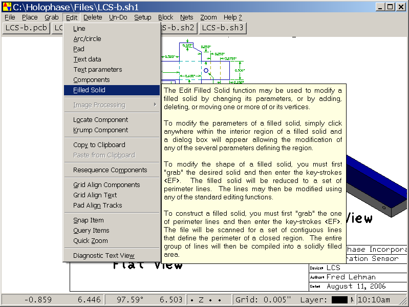
Pop-up Context Help
Menus, dialog boxes, data files, and working functions all have individual
context help messages to aid in smooth and easy operation for both the novice
and seasoned professional. Many trivial or intrinsically obvious items will,
of course, have only a short explanation, but the more complex functions
are accompanied by an appropriate description, some even have a helpful
illustration.
|
|
|
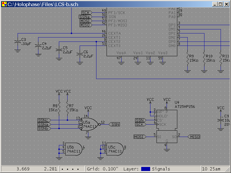
Schematic Drawing Sheets
Schematics are quick and simple with built-in libraries for standard components
and symbols. Named signals are easily identified with label tags that work
across multiple data sheets. Power and ground connections are made trivial as well.
|
|
|
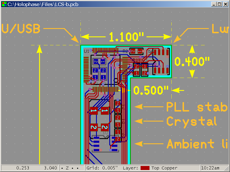
PCB Layout Diagrams
CIRCAD places no restrictions upon your printed circuit board as to content,
size, or layer count. The example shown at the right is a 4-layer board that
has a total of fourteen source layers for additional goodies such as keep-out
regions, dimension lines, and component location identifiers.
|
|
|
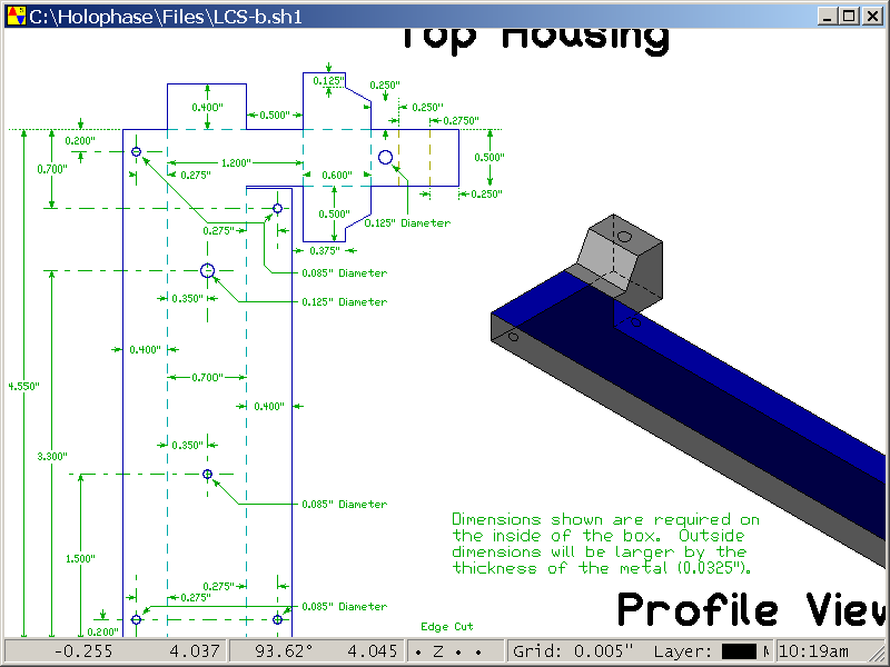
Mechanical Drawings
No longer is it necessary to maintain a separate (and difficult to use) mechanical
drawing package to create blueprints for the chassis or packaging to house your
products. CIRCAD has specialized elements for Center Lines, Dotted Lines, Dashed
Lines, and Dimension Lines. Dimension lines are automatically re-scaled if they are
moved after their initial placement.
|
|
|
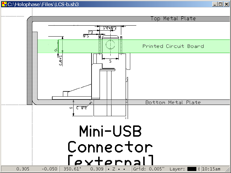
Assembly & Manufacturing Drawings
To ensure a proper fit at assembly time, the actual data from component
manufacturers can be included into your orthographic assembly drawings. In
the example shown at the right, a detail drawing of a USB connector was
snipped out of the PDF file from an OEM data sheet and pasted into the CIRCAD
assembly drawing. The "picture" of the component was then resized so that its
own supplied dimensions matched the real world. CIRCAD drawing elements are
placed on top of the background pictures. Note the use of transparent fills
to represent the PCB and the metal chassis.
|
|
|